The use of a “safety” Smart Flag must be used if, in the opinion of the Inspector, a defect impacts the integrity of the structure to such a degree that the safety of the public or structure are jeopardised. The addition of a smart flag and deterioration process assessment to the main damages of the bridge, is necessary to give in-depth view and evaluate bridge reliability and safety. Safety is defined as user safety, and the outcome (failure mode) is always an accident. The evaluation method of reliability is connected to failure modes in vulnerable zones of a structures and quantitative modelling of bridge damage processes.
By accurately identifying defects, potential failures can be predicted. As a Bridge Inspector, it is crucial to flag these defects with relevant comments, highlighting elements that require urgent attention or further structural assessment.
Observing a defect on a bridge often indicates active damage processes. Analyzing these processes and their relationship to the observed defects helps identify the root causes. Understanding damage processes is essential for predicting performance, planning preventive maintenance, and considering potential rehabilitation. Reliable information on these processes allows for optimised inspection and maintenance strategies, aligned with the exposure classes defined during the design phase.
Vulnerable Zones
To assess deterioration processes, the evaluation should be tailored to the type of damage, its cause, and the material of the affected structural element. Most damages can be linked to specific defects or observations. However, some damages are merely symptoms and do not impact the structure’s reliability.
Nearly all deterioration processes related to concrete structures can affect any part of a concrete bridge. However, it is important to note that not all parts of the bridge are equally critical in terms of consequences. For example, load-bearing elements have regions that are particularly vulnerable and require special attention, which will be discussed further.
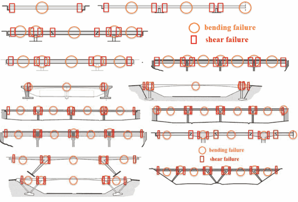
The proposed segmentation of the superstructure in the longitudinal direction (partitioning of an element into regions with different vulnerability) is based on the Concrete Details Vulnerability Manual, and the Long-Term Bridge Performance Program Protocols, Version 1:
- High moment regions
- Sagging (label HMS region)
- Hogging (label HMH region)
- High shear regions (label HS region)
- Construction joint (rigid type) (label CJ region)
- Shear key (label SK region)
- Hinges (label HG region)
- Anchorage zones (label AN region)
 Vulnerable zones for different types of girder and frame bridges
Conceptual weaknesses may also be associated with some of the above-mentioned vulnerable zones. One such example is poor shear capacity in high shear regions in old concrete bridges. This conceptual weakness is due to limited understanding of the shear phenomena given in old design codes.
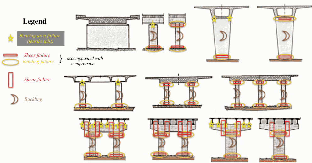
Furthermore, it should be noted that elements of substructure support the superstructure, implying that their failure might lead to a total collapse. In general, a substructure might fail in crushing or buckling failure mode. In addition, bearing areas are exposed to splitting forces. Pier caps (if they exist) are generally exposed to high shear stresses making them particularly vulnerable. Elements of substructures are mainly exposed to sudden events e.g., impact, scour and earthquake. Typical locations of vulnerable zones related to piers are presented below along with their relationship to an anticipated failure mode.
 Vulnerable zones related to substructure
In addition to load beading function there is the elements that gives protection of comfort, these elements are related to nearly all bridge types. It should be noted that malfunction of these elements might jeopardize the load-bearing elements of the bridge (durability issues) and/or impose severe consequences themselves. The level of service generally depends on the adequate function of these elements (traffic safety issues). Below, vulnerable areas are listed as checklists that may be used during inspection.
- Bearings
- Sufficient ability to allow movement, considering the temperature of the superstructure.
- Correct position of the bearings themselves and parts of the bearing relative to each other.
- Uncontrolled movement of the bearing, as predicted by Movement Indicator provided in slide-guide and Free Bearing (Pot & Spherical).
- Fracture, cracks, and deformations of parts of the bearings.
- Cracks in the bedding or in adjacent parts of sub- and superstructure.
- The condition of the anchorage.
- The condition of sliding or rolling surfaces.
- The condition of the anticorrosive protection against dust, and of the sealings.
- Concrete hinges
- Developed more than 100 years ago and if correctly executed they perform very well throughout the world. Concrete hinges are characterised by high load- carrying capacity and a moderate rotational capacity. Concrete cracking in the throat of the Freyssinet (un-reinforced) hinge and risk of impact shear loading in the Mesnager (reinforced) hinge are important considerations when assessing or predicting concrete hinge performance.
- Expansion Joints
- Damage to the anticorrosive protection.
- Cracks due to fatigue in steel members.
- Damage to seals.
- Workability of the linkage (proper function).
- Obstruction or damage of the drainage system
- Drainage
- as a sub-component of the equipment category, comprises of permanently installed drains and the associated piping systems. The inspection should verify proper deck slopes and proper functioning of kerb channels, drainage inlets, pipes and outlets, and possible drain holes for drainage of voids. Blockage of drainage may create a serious traffic hazard as well as result in severe deterioration.
- Waterproofing is usually not visible, i.e., the condition has to be assessed from possible consequential damage on the neighbouring components such as:
- Leaking decks/wet spots beneath superstructure
- Finding of protective concrete wash out
- Swelling of the pavement
- Cracking of the pavement
- Pavement/Overlay
- Cracks, unevenness, holes, and swelling
- Rutting
- Lack of friction
- Joint failure
- Improper drainage
- Barriers, windscreens, and signs
- Damages from impact
- The condition of the anticorrosive protection
- Missing or loose bolts
- The condition of the anchorage
- The condition of the concrete
- Visual appearance (readability, reflection, lighting etc.)
- Installations typically comprise of lighting (typically light poles), electro-mechanical dehumidification systems (primarily on signature bridges), Structural Health Monitoring Systems (primarily on signature bridges), hydraulic opening arrangement, and possible utility lines fixed/fastened on the bridge. Their vulnerability shall be evaluated case by case.
Hidden Defects
Sudden weight restrictions and emergency closures on roadway bridges are often because of hidden defects. These defects that are hidden from sight (inspection within touching distance) or are not obvious on the first observation/inspection. A guidance for detecting and managing hidden defects in bridges consists of a three-step procedure comprising of risk review, risk assessment, and risk management. As part of the risk review, two key questions must be asked during the review of existing information: “What do the records say?” and “What is not recorded?” Also, two questions must be asked on site during inspections: “What can I see?” and “What can I not see?”
The typical hidden defects for concrete girder and frame roadway bridges can be summarised as:
- Superstructure
- Within the concrete body
- Reinforcement
- Prestressing wires/stands and anchorages
- Voided and cellular structures
- Half-joints
- Obscure surfaces
- Concrete hinges
- Temporary works
- Bearings and expansion joints
- Poor access
- Inspection at the ‘wrong time’
- Un inspectable items
- Drainage
- Waterproofing
- Substructure
